Most alloys and their microstructures have been developed over recent decades to provide the desired mechanical performance at room and elevated temperatures. However, fewer material options exist for high-strength and damage-tolerant cryogenic applications, despite the less severe cost restrictions in this field2,3. For instance, precipitation hardening has been one of the most successful strategies to enhance the strength of alloys, by impeding dislocation motion, which leads to higher loads for maintaining inelastic deformation4,5,6,7,8. However, under cryogenic conditions, this approach comes at the expense of ductility, owing to formation of dislocation pile-ups and high stress concentrations at the precipitate–matrix interfaces, both features that promote damage initiation at these sites9,10. The formation of coherent precipitates (for example, the L12 long-range-ordered (LRO) phase in some face-centred cubic (fcc) materials) can to some extent reduce the damage initiation tendency owing to the lower interfacial energy compared with that for incoherent and semi-coherent interfaces11. However, an intense heterogeneous stress field can still develop when the size of these precipitates becomes sufficiently large after prolonged ageing, owing to a high anti-phase boundary energy and the formation of dislocation loops around them impeding the ensuing dislocation motion9,12,13.
In contrast to these well-established hardening mechanisms and their inherent disadvantages that are known from conventional dilute alloys, the impact of subnanoscale chemical short-range ordered (SRO) features on mechanical properties has been less understood14,15,16. These atomic ordering clusters seem to form in some medium- and high-entropy alloys (MEAs and HEAs) as a result of a subtle interplay between local enthalpic interactions among the constituent elements and the otherwise entropy-dominated solid solution on which these alloys are based14. The highly dispersed and uniformly distributed SRO zones, along with their suppressive effect on easy dislocation glide and the associated low stress and strain heterogeneity16,17,18, turn out to be an ideal strengthening mechanism at cryogenic temperatures, although the underlying strengthening mechanisms and their tunability have remained elusive so far14,15,16. However, with respect to the influence on strain-hardening capacity (ensuring uniform elongation), SRO domains seem to be less effective than LRO domains15,19. This discrepancy between appreciable stress increase and insufficient strain hardening motivates us to develop a rationale design concept for dual-scale chemical ordering. In this context, we show that a fine balancing of two types of nanoscale ordered structures and a massive solid-solution matrix design can become a key approach for the development of high-performance metallic materials for cryogenic applications.
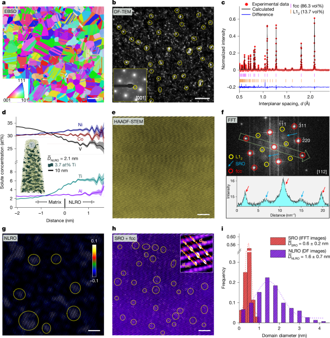
We realize this nanostructure design strategy in a CoNiV-based alloy, with a nominal composition of Co32Ni32V32Al2Ti2 (at%), hereafter referred to as CoNiV-AlTi. The enthalpic interactions of vanadium (V) with cobalt (Co) and nickel (Ni), as well as their significant mismatch in atomic size and shear modulus (Supplementary Table 1), promote the formation of local chemical short-range ordering17,20. Among the frequently added microalloying elements, aluminium (Al) and titanium (Ti) have the most negative enthalpy of mixing with the main elements (Extended Data Fig. 1), which strongly enhances the tendency for the formation of long-range ordering21,22. A careful thermodynamically guided solid-solution and ageing treatment is next required to bring these two types of enthalpy-dominated ordering state into co-existence with the entropy-dominated massive solid-solution matrix, without transitioning into a state of intermetallic or larger precipitate formation (Supplementary Fig. 1). The so-treated alloy has a recrystallized and chemically homogeneous fcc matrix (Fig. 1a and Supplementary Fig. 2) with a high number density (approximately 4.5 × 1025 m−3) of nanoscale L12 long-range ordered (NLRO) domains, as shown in the dark-field transmission electron microscopy (DF-TEM) image (Fig. 1b). The average size of the NLRO domains is 1.6 ± 0.7 nm, which is at least half an order of magnitude smaller than L12-structured precipitates often observed in some MEAs and HEAs or high-strength steels (normally above 5 nm)22,23,24. The fraction of the nanoscale L12 domains occupies 13.7 vol%, as determined from neutron diffraction experiments and Rietveld refinement analysis (Fig. 1c). Atom probe tomography (APT) analysis reveals an enrichment of Ti and Ni in this domain (Fig. 1d). On the basis of the thermodynamic calculation (Extended Data Fig. 1), these NLRO domains are the early-stage precursor states of close-packed Ni3(Ti, Al)-type L12 precipitates that are typically formed by spinodal decomposition. The determined average Ti content of the NLRO domain (6.2 at%) is lower than that predicted by thermodynamic calculations (15.7 at%, according to the TCHEA4 database and the Thermo-Calc software), owing to the limited ageing time applied in our case, that is, equilibrium partitioning by purpose has not been obtained, to reach atomic-scale ordering without transition into the full equilibrium precipitation state. Such restricted compositional contrast between the NLRO domains and the matrix yields an ultralow lattice mismatch of 0.04% between the two phases, as revealed by neutron diffraction.
a, Electron backscatter diffraction (EBSD) inverse pole figure showing the fcc matrix with an average grain size of 11.2 ± 1.3 μm. b, DF-TEM image showing the presence of NLRO zones. The inset is the selected-area electron diffraction (SAED) pattern taken from the [001] zone axis, and the DF-TEM image was taken from one of the superlattice spots marked by the yellow dotted circle in the SAED pattern. c, Neutron diffraction pattern showing the fcc and L12 peaks. The calculated weight fraction of L12 phase was converted to the volume fraction. d, APT proximity histogram concentration profile across the matrix–NLRO interface based on a 3.7 at% Ti iso-concentration surface. The shaded regions are error bars corresponding to their coloured lines (element distribution). Inset: the iso-concentration surface map for Ti. e,f, Atomic-scale HAADF-STEM image along the [112] zone axis (e) and the corresponding FFT pattern collected from one fcc grain (f). Inset in f: the intensity profile along the light green arrow marked in the FFT pattern. g,h, IFFT image transformed from the NLRO (g) and SRO (h) spots in the FFT pattern in f. Some typical NLRO and SRO domains are marked by yellow dotted circles. Inset in g: scale bar for the normalized NLRO intensity. Inset in h: an enlarged region showing the detailed lattice structure of a SRO domain and the fcc matrix. i, Distribution of the size of NLRO and SRO domains, which was statistically analysed based on DF-TEM images and IFFT images, respectively. Scale bars, 10 μm (a), 20 nm (b), 2 nm (e,g,h).
Figure 1e shows a representative atomic-resolution high-angle annular dark-field scanning transmission electron microscopy (HAADF-STEM) image of the alloy, taken along the [112] zone axis, with the corresponding fast Fourier transform (FFT) pattern shown in Fig. 1f. In addition to the sharply concentrated spots in the FFT image that represent the presence of the L12 structure (marked by yellow circles in Fig. 1f), we also observe bright diffuse reflections, which locate at positions corresponding to \(1/2\{\bar{3}11\}\) (indicated by the blue arrows in Fig. 1f). Such diffuse reflections, combined with machine-learning-enhanced APT (ML-APT) analysis (Extended Data Fig. 2), represent the presence of the L11-structure SRO, which mainly originates from the nearest-neighbour preference towards unlike element pairs (such as V–Co or V–Ni pairs17). The inverse FFT (IFFT) images transformed from the L12 and SRO reflections provide the size and distribution of these two classes of ordered structures (Fig. 1g,h), indeed revealing the co-existence of both types of nanoscale ordering structure features in one local region of an fcc grain. Compared with NLRO, the size of the SRO domains is much smaller, namely, about 0.6 ± 0.2 nm (Fig. 1i), thus assuming atomic-scale dimensions, and more densely distributed (number density about 2.4 × 1026 m−3). The existence of a high density of these ordering domains effectively reduces the dislocation mean free path, therefore increasing the critical resolved shear stress for dislocation gliding (Supplementary Note 1). This pushes the limits of rational thermodynamic nanostructure design of complex alloys into atomic-scale regions.
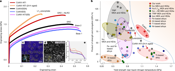
The introduction of dual-scale local chemical ordering and their careful size control result in an exceptional strength (yield strength about 1.2 GPa, ultimate tensile strength about 1.8 GPa) and ductility (fracture strain about 42.6 %) in our CoNiV-AlTi alloy at cryogenic temperature (87 K), as shown in Fig. 2a. Figure 2b reveals that at the same yield strength level, the product of strength and ductility of our alloy has surpassed corresponding reference values of other metallic materials (by about 60%) that have already been used or have potential to be used in cryogenic applications, including various HEAs and MEAs and more conventional Ti-based, Ni-based, Fe-based and Al-based alloys. A notably high fracture toughness (338.4 MPa m0.5) is also achieved at 87 K using our dual-scale ordering strategy (Extended Data Fig. 3).
a, Engineering stress–strain curve of our CoNiV-AlTi sample with a dual-scale ordering structure, compared with the base CoNiV(SS) and CoNiV-AlTi(SS) samples, the CoNiV(SSA) sample, and the aged CoNiV-AlTi sample containing large-sized (about 25 nm) L12 precipitates. c, IFFT image of the CoNiV(SSA) sample, showing the presence of SRO and its size and distribution. d, DF-TEM image of the 24-h aged CoNiV-AlTi sample, showing the presence of large-sized L12 precipitates. e, Strain-hardening-rate curves. The grain size of all these materials is similar (Supplementary Fig. 5). b, The product of tensile strength and total elongation as a function of yield strength of the CoNiV-AlTi alloy (at 87 K) with different grain sizes (Supplementary Fig. 6), compared with other high-performance alloys used or planned to be used in cryogenic applications, including various MEA and HEAs (for example, single-phase fcc MEA/HEAs, fcc MEA/HEAs with L12 or B2 ordered phases, transformation-induced plasticity (TRIP) MEA/HEAs, and body-centered cubic (bcc) MEA/HEAs), Fe-based alloys, Ni-based alloys, Al-based alloys and Ti-based alloys. All the data in this figure are from samples tested at near liquid-nitrogen temperature (77–110 K), and the associated details are listed in Supplementary Table 3. The error bars represent standard deviation. Scale bars, 1 nm (c), 50 nm (d).
To investigate the respective contribution of the SRO and NLRO domains on the cryogenic mechanical properties, we further compare our alloy with (1) an equimolar CoNiV base-alloy that is solid-solution treated (hereafter referred to as CoNiV(SS)), (2) a likewise solid-solution-treated CoNiV-AlTi sample (hereafter referred to as CoNiV-AlTi(SS)), and (3) a solid-solution-treated and aged CoNiV sample (hereafter referred to as CoNiV(SSA)). The first two types of material, directly quenched from high temperature (1,100 °C) at which the entropy-driven configurational intermixing exceeds the enthalpy-driven ordering effects14, contain a low possibility of SRO-domain formation (see the TEM results in Extended Data Fig. 4). We note that Al and Ti in solid solution (about 2 at% for each element) only slightly increase the yield strength (by 27 MPa) under cryogenic temperature loading conditions (Fig. 2a), but do not significantly alter the materials’ stacking fault energy (SFE) or their elastic properties (Extended Data Fig. 5 and Supplementary Table 2). Both, the CoNiV(SS) and CoNiV-AlTi(SS) samples are thus regarded as ordering-free base materials for comparison. The CoNiV(SSA) sample, aged at 750 °C, contains only SRO domains with a similar domain size and volume fraction as that in our alloy (Fig. 2c). Further thermodynamic assessment and ML-APT analysis, as shown in Supplementary Fig. 3 and Extended Data Fig. 6, also confirm the likelihood of the formation of SRO domains with both L11 and L12 atomic configurations in the CoNiV(SSA) sample.
The comparison between the CoNiV(SS) and CoNiV(SSA) specimens reveals that the presence of SRO markedly increases the cryogenic yield strength (by about 140 MPa) but does not affect the alloy’s strain-hardening ability (Fig. 2e). Such an increase in yield strength is attributed to the additional energy barrier associated with the creation of diffuse anti-phase boundaries when dislocations pass through such SRO regions16,25. When NLRO domains are also introduced into the material (that is, our CoNiV-AlTi sample), the NLRO-induced enhancement in yield strength is about 167 MPa, with a similar strengthening mechanism as that from SRO domains18,26. Moreover, the strain-hardening rate is simultaneously elevated (by about 1,000 MPa) owing to the presence of NLRO domains, a key factor for the sustained ductility at cryogenic temperature. The introduction of the (sub)nanoscale ordering structure does not result in a significant ductility loss at cryogenic temperature exposure, which is in sharp contrast to a sample that is aged for prolonged time (24 h) to form larger ordered L12 precipitates with an average size of about 25 nm (Fig. 2d). For the latter sample, the increased lattice misfit (0.15%; Extended Data Fig. 7) between the L12 precipitates and the matrix, resulting from the larger precipitate size and the higher degree of compositional contrast, leads to an increase in the interfacial energy27 as well as in stress concentrations at the precipitate–matrix interfaces9,12,13. These factors promote early crack nucleation, particularly at cryogenic temperatures (Supplementary Fig. 4), which results in a significantly reduced ductility of this sample (only about 22%; Fig. 2a).
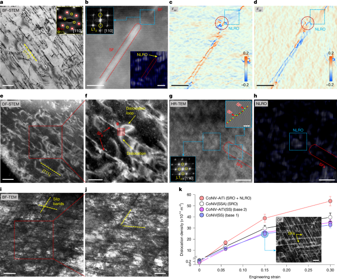
Next, we unravel the cryogenic strain-hardening mechanisms and the associated effects of NLRO domains in our CoNiV-AlTi alloy. For this purpose, we deform the sample at different strain levels and probe the substructure by TEM. Planar-slip substructures consisting of numerous stacking faults (SFs) along the {111} planes are observed at a small strain of 6% (Fig. 3a). We frequently observe strong L12 diffraction signals at regions in-between two SFs (see a typical micrograph in Fig. 3b). The IFFT analysis (inset in Fig. 3b) transformed from such reflection signals reveals the existence of relatively large, structurally intact (that is, undestroyed by dislocation slip) NLRO domains in these regions. We further analyse the elastic strain fields for the region shown in Fig. 3b, containing two consecutive SFs and a large NLRO domain in-between. Notably, a high elastic strain concentration is observed at the end of the SF, where the SF interacts with the NLRO domain (marked by a dashed red circle in Fig. 3c,d). Similar phenomena have also been observed in other regions of different grains, whereas such elastic strain concentration is not observed in the ordering-free CoNiV(SS) sample deformed to the same strain level (Extended Data Fig. 8). Hence, this feature strongly suggests a blocking effect of NLRO on the motion of partial dislocations.
a–j, Images of the substructure of the CoNiV-AlTi alloy cryogenically (87 K) deformed at 6% (a–d), 15% (e–h) and 30% (i,j) strain. a, Bright-field (BF) STEM image showing the formation of SFs along {111} slip planes. Top-right inset in a: the corresponding SAED pattern. b, Atomic-scale low-angle annular dark-field STEM image, the corresponding FFT pattern and the IFFT image, showing the existence of non-destructed NLRO domain in-between two SFs. Bottom-right inset in b: the IFFT image showing the distribution of NLRO. Top-left inset in b: the FFT pattern from the corresponding light blue dashed box. c,d, The distribution of elastic strain in horizontal (εxx; c) and vertical (εyy; d) directions for the same area in b, revealing the interaction between the NLRO domains and the SFs. The red dashed circle highlights the high elastic strain concentration close to a NLRO zone that is marked by a blue dashed square. e, DF-STEM image showing non-planar dislocations and dislocation loops between slip bands. f, The enlarged figure from the corresponding red dashed box in e. g,h, High-resolution TEM (HR-TEM) image (g) and the corresponding IFFT image (h) taken from the region marked in f, showing the blocking effect of the NLRO on dislocation gliding. Bottom-left inset in g: the FFT pattern transformed from the corresponding marked region. Top-right inset in g: the filtered HR-TEM image from the corresponding marked region. i, BF-TEM micrograph showing the high dislocation density between the slip bands. j, The enlarged figure from the corresponding red dashed box in i. k,The evolution of dislocation density as a function of plastic strain, compared with ordering-free CoNiV(SS) and CoNiV-AlTi(SS) samples and the SRO-domain-containing CoNiV(SSA) sample. Scale bars, 200 nm (a,j,k,inset), 5 nm (b,c,d,g,h), 100 nm (e), 50 nm (f), 500 nm (i).
With further deformation (for example, at 15% strain), a considerable fraction of non-planar dislocation slip is observed between slip bands (Fig. 3e). This is a unique feature that is not observed in the ordering-free CoNiV(SS) sample or the CoNiV-AlTi(SS) sample, when comparing the deformation microstructure of grains with similar orientation relative to the loading direction (Extended Data Fig. 9). These non-planar dislocations are typically emitted at the points where SFs encounter the NLRO domains and experience a high resistance for their further motion (as shown in Fig. 3g,h). The pinning of the leading partials by NLRO can serve as starting points for partial dislocation recombination, double cross-slip and Frank–Read sources, resulting in the nucleation of new dislocation loops, as shown in Fig. 3f. The active gliding of these non-planar dislocations indicates the occurrence of cross-slip of screw dislocations at this strain level (see more detailed dislocation analysis in Supplementary Figs. 7 and 8). This finding is further supported by the presence of a higher fraction of screw dislocations in this alloy compared with the reference ordering-free CoNiV(SS) and CoNiV-AlTi(SS) samples as well as the SRO-domain-containing CoNiV(SSA) sample at the same strain level (revealed by the higher dislocation character parameter q: 1.9 for the CoNiV-AlTi sample than the other three samples, determined based on the neutron diffraction data; see Supplementary Figs. 9 and 10). This effect releases local stress concentrations that would otherwise build up owing to deformation localization28,29,30. Further gliding of these dislocations will eventually trigger their mutual interactions and the interaction with the existing slip bands, resulting in a high density of dislocation networks between the dislocation bands (as shown in the microstructure at 30% strain demonstrated in Fig. 3i,j). The influence of NLRO domains on dislocation evolution and patterning is schematically illustrated in Extended Data Fig. 10d.
The deformation-driven evolution of the dislocation density of the investigated materials is shown in Fig. 3k. The NLRO-containing CoNiV-AlTi sample shows a higher rate of dislocation multiplication compared with the reference samples with and without SRO. The more rapid dislocation multiplication, owing to the blocking effect of NLRO on partial dislocation gliding and thus the necessity for new dislocation generation and the subsequent dislocation interactions, serves as an important contribution to the higher strain-hardening rate at cryogenic temperature (Fig. 2a). According to the Taylor hardening law31,32, the stress increase owing to strain-hardening can be expressed as: \({\sigma }_{{\rm{f}}{\rm{l}}{\rm{o}}{\rm{w}}}-{\sigma }_{{\rm{Y}}{\rm{S}}}={a}_{0}MGb\sqrt{{\rho }_{\text{d}}}\), where σflow and σYS are the flow stress at a given plastic strain and the yield strength, respectively, ρd is the dislocation density (the initial dislocation density of recrystallized samples can be neglected), and α0 (dimensionless constant), G (shear modulus), M (Taylor factor) and b (magnitude of the Burgers vector) are regarded as constants that do not vary much during tensile deformation33,34. On the basis of the measured dislocation density (Fig. 3k), the deformation-induced stress increase for the NLRO-domain-containing CoNiV-AlTi sample is estimated to be 1.29-times higher than that of the ordering-free CoNiV(SS) sample, at the same global strain of 30%. This value is very close to the result directly acquired from the tensile tests (about 1.26), which confirms the dominant role of NLRO-domain-affected dislocation multiplication on strain hardening of the studied materials.
The traditional view on the promoting role of small-scale local ordering on materials’ strain hardening is based on the shearing of ordered phases by gliding dislocations13,35,36. The associated local destruction of the ordered structure produces a glide-plane softening effect driven by the energetically favourable elimination of the introduced high-energy anti-phase boundaries36. Such an effect promotes dislocation planar slip by facilitating trailing dislocation gliding on the same slip planes16,36. Although we do observe such a dislocation shearing phenomenon and the resulting destruction of NLRO domains along the gliding paths at higher strains (for example, 30%; Extended Data Fig. 10a–c), we believe that this mechanism results in only a moderate influence on the alloy’s strain-hardening rate, owing to the following two factors. First, owing to the reduced SFE at cryogenic temperatures5,37, planar dislocation slip is already the prevalent deformation mode for the CoNiV-based alloys, regardless of the existence of local ordering (Extended Data Fig. 9). Second, the existence of SRO domains is expected to have an effect on SFE and dislocation slip planarity16, but by itself does not promote a notable increase in the strain-hardening rate of the CoNiV(SSA) sample at cryogenic temperature (Fig. 2a, the comparison between CoNiV(SS) and CoNiV(SSA) samples). In addition, owing to the extremely small size (below 1 nm), SRO can be readily destroyed by only a few pairs of dislocations once they are nucleated and start to glide18. Thus, SRO domains are not expected to significantly influence dislocation patterning during plastic deformation in the investigated alloys. This explains the similar evolution of the overall dislocation density observed between the SRO-domain-containing CoNiV(SSA) sample and the ordering-free CoNiV(SS) sample at the same strain level (Fig. 3k). This deficiency of SRO domains as a stand-alone hardening mechanism can be compensated by the additional introduction of NLRO phases. The latter mechanism also allows to alter the dislocation pattern and population, but without producing substantially heterogeneous stress fields.
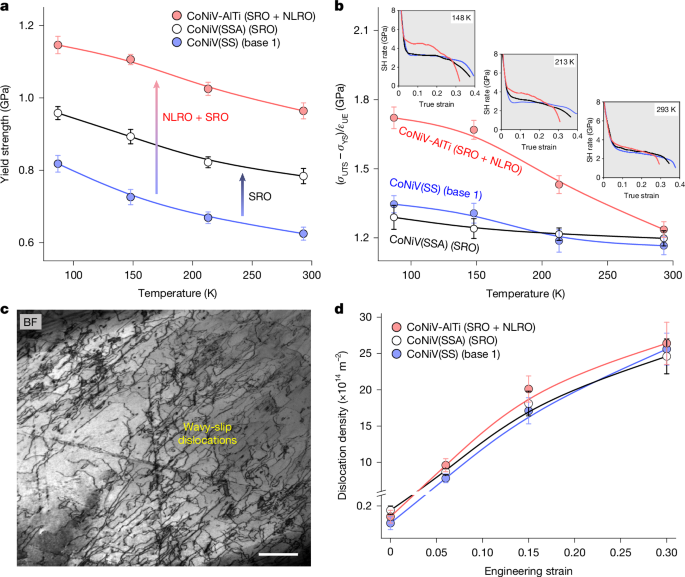
We further evaluate the temperature dependence of the effectiveness of such a microstructural approach. Mechanical tests show that compared with the CoNiV(SS) and CoNiV(SSA) reference samples, the combination of SRO and NLRO domains can elevate the alloys’ yield strength at temperatures up to ambient temperature (Fig. 4a). However, the effects on strain-hardening capability gradually vanish with higher testing temperatures (Fig. 4b), similar to some alloys containing coherent nanoprecipitates38,39, indicating a weaker interaction between NLRO domains and dislocations. Unlike the deformation substructure observed at cryogenic temperature, the deformation mode of the CoNiV-AlTi alloy at room temperature shows a limited planar dislocation slip behaviour, and, instead, wavy dislocation slip is prevalent at this temperature owing to the increased SFE (as shown in Fig. 4c). The higher tendency for dislocations to cross-slip at increased temperatures40,41, as well as the temperature-dependent anti-phase boundary energy42, decreases their interaction with the NLRO obstacles, which means that the presence of NLRO domains has little influence on dislocation multiplication and patterning at elevated temperatures. This is strongly supported by the nearly unchanged evolution of dislocation density between the SRO + NLRO-domain-containing CoNiV-AlTi sample and the ordering-free CoNiV(SS) sample deformed to a same strain level at room temperature (Fig. 4d). This analysis reveals a strong dependence of ordering-induced strain-hardening enhancement on testing temperature, SFE and the associated dislocation gliding modes, which provides a fundamental guideline for the selection of material systems and their operating scenarios that can benefit from our ordering and microstructure design approach.
a, The relation between yield strength and testing temperature. b, The value of (σUTS − σYS)/εUE (characterizing the alloy’s strain-hardening (SH) ability, where σUTS and εUE are ultimate tensile strength and uniform elongation, respectively) as a function of testing temperature. c, BF-TEM image of the NLRO-containing CoNiV-AlTi sample deformed to 6% strain at room temperature. d, The deformation-induced evolution of the dislocation density for the three samples strained at room temperature. The error bars represent standard deviation. Scale bar, 500 nm (c).
To conclude, we show here that a dual-scale short- to long-range chemical ordering strategy can substantially improve the mechanical properties of metallic alloys at cryogenic temperatures. The two types of ordered structure confine the dislocations’ mean free path and provide both a higher friction stress (lending strength) and a more rapid dislocation multiplication rate (enhancing the strain-hardening ability) at cryogenic temperatures, as opposed to reference samples without the presence of such an ordering hierarchy. This (sub)nanoscale microstructure strategy is different from the widely adopted precipitation hardening approach, which creates local stress peaks that can lead to damage initiation. We have also validated the effectiveness of the dual-scale chemical ordering approach on improving the cryogenic strength–ductility synergy in NiCrFe-based and CoCrNi-based MEAs (as shown in Supplementary Figs. 11 and 12), demonstrating the generality of our concept. Our work hence widens the microstructure design toolbox that so far lacked effective means for enabling alloys to withstand harsh cryogenic environments.


